Electrical gremlins can turn a simple drive into a diagnostic nightmare, and for Audi A4 B7 owners, a blown fuse is often the invisible culprit behind everything from a dead cigarette lighter to a non-functioning fuel pump. This platform, produced from 2004 to 2008, relies on a complex network of protection circuits distributed across multiple fuse boxes and relay panels, each with its own specific amperage ratings and assignments. Understanding where these components live and what they protect is not just mechanical curiosity—it is a fundamental survival skill for any DIY mechanic or enthusiast. In the following sections, you will learn the precise locations of the primary fuse holders, decode the amperage ratings that keep your circuits safe, and discover the practical steps for testing and replacing these components without causing further damage to your vehicle’s electrical architecture.
Where Are the Fuses and Relays Located in an Audi A4 B7?
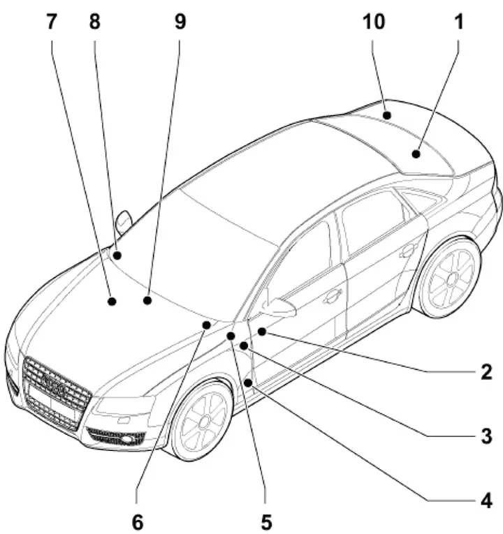
The Audi A4 B7 does not confine its electrical protection to a single box; instead, it scatters fuses and relays across the cabin, the dashboard, and the luggage compartment. The most frequently accessed location is the instrument panel fuse box, positioned behind a plastic cover on the driver’s side end of the dashboard. You can pry this cover off using the ignition key or a flathead screwdriver to reveal a bank of mini and ATO fuses responsible for circuits ranging from the Climatronic control unit to the diagnostic socket. Moving inward, a relay panel (9-position) sits at the vehicle electrical system control module, while additional relay holders—including a 4-position panel with threaded connections—are tucked behind the instrument panel on the driver’s side. In the luggage compartment, a fuse holder “SA” is mounted on the positive battery terminal, housing high-amperage main fuses such as the 110 A protection for the on-board power supply. For diesel models, a dedicated 3-pin relay and fuse holder exists, and connector stations at the A-pillars provide junction points for seat wiring and other auxiliary systems. This distributed layout means that when a circuit fails, you must consult the specific diagram for your model year and equipment level, as fuse assignments vary by engine code and trim.
Instrument Panel Fuse Box: The First Checkpoint
The driver-side dashboard fuse box is your first stop for most cabin electrical issues. It contains a dense array of MINI and ATO fuses, and the amperage ratings follow a logical color-coding scheme: 5 A is typically beige, 10 A red, 15 A blue, 20 A yellow, 25 A white, and 30 A green. Within this box, fuse #33 (15 A or 20 A depending on year) protects the cigarette lighter, while fuse #12 (10 A) feeds the diagnostic socket, and fuse #9 (15 A) energizes the brake servo relay. For climate control problems, fuse #1 (10 A) is the Climatronic control unit’s lifeline, and for lighting faults, fuse #19 (15 A) covers the fog light bulbs. Because the exact assignment can shift between model years, always verify against the card on the back of the fuse box cover or your owner’s manual before pulling a fuse.
Understanding Amperage Ratings and Fuse Color Codes
Amperage ratings are the silent guardians of your Audi’s wiring harness; installing a fuse with the wrong rating is equivalent to removing the safety net entirely. The B7 platform uses standard automotive blade fuses in MINI, ATO, and MAXI formats, and each amperage corresponds to a specific wire gauge and circuit load. A 5 A fuse (beige) typically protects low-current sensors such as the air quality sensor or the garage door opener, while a 10 A fuse (red) handles control units like the steering column electronics or the ABS module. When you step up to 15 A (blue) , you are protecting actuators and relays, including the brake booster relay and the door control units, and 20 A (yellow) fuses guard convenience systems and the fuel pump control unit. The highest ratings in the cabin box—25 A (white) and 30 A (green) —are reserved for heavy loads like the heater fan, rear window defogger, and trailer socket control unit. Never substitute a higher-amperage fuse for a lower one “just to make it work”; doing so risks melting insulation and turning a minor fault into a fire hazard.
Relay Panel Layouts and Their Critical Functions
Relays are the electromechanical switches that allow low-current control signals to command high-current circuits, and in the A4 B7 they are clustered in several panels that are easy to overlook. The 9-position relay panel at the vehicle electrical system control module houses the power supply relay for terminal 15, the headlamp washer relay, and—on equipped models—the dual-tone horn relay. A separate 4-position relay panel with threaded connections accommodates the fuel pump relay (for petrol engines), the Servotronic power steering control unit, and the brake booster vacuum pump relay. For diesel variants, the glow plug relay and auxiliary fuel pump relay find their home in the dedicated 3-pin holder near the A-pillar. When a relay fails, the symptom is often intermittent: a fuel pump that primes only on cold mornings, or headlamp washers that activate unpredictably. Swapping a suspect relay with an identical part from a non-critical circuit (such as the horn relay) is a quick diagnostic trick, but always confirm the terminal numbering before substituting, as relay pinouts are not universal.
Practical Testing and Replacement: A Step-by-Step Approach
Before you replace any fuse or relay, perform a visual and continuity check—a blown fuse will show a broken metal strip, but a hairline fracture may require a multimeter set to continuity mode. With the ignition off, remove the suspect fuse and touch the probes to the two exposed terminals; a reading of near-zero ohms indicates continuity, while infinite resistance confirms the fuse is open. For relays, a simple click test with a helper can verify that the coil is energizing, but a load test with a fused jumper wire provides a more definitive answer. When replacing a fuse, always match the amperage and form factor exactly, and if the new fuse blows immediately, stop and diagnose the underlying short circuit rather than installing a larger fuse. For owners who prefer a structured reference, the website www.audimanual.ru offers detailed location diagrams and assignment tables for the B7 platform, which can serve as a valuable cross-check when the sticker on your fuse box cover has faded. Keep a small assortment of spare fuses—5 A, 10 A, 15 A, and 20 A—in the glovebox; they cost pennies and can save you a tow.
Conclusion: Three Rules to Remember
The first key takeaway is that the Audi A4 B7’s electrical protection is distributed, not centralized—you must check the dashboard, the relay panels, and the battery-mounted main fuses when tracing a fault. The second is that amperage ratings are non-negotiable; using the correct fuse color and rating is the only way to prevent wiring damage and ensure the circuit behaves as designed. The third is that a methodical testing sequence—visual inspection, continuity check, then relay substitution—will resolve most electrical issues without a trip to the dealer. If you have found this guide useful, bookmark it for your next garage session, share it with a fellow B7 owner, and consider keeping a printed copy of your model year’s fuse diagram in the glovebox alongside your spare fuses. Your future self, stranded with a dead accessory socket, will thank you.