Understanding the Tahoe’s Electrical Protection System
The third-generation Chevrolet Tahoe uses a distributed electrical system designed to protect wiring, control modules, and electrical consumers against overloads and short circuits. Known as the GMT900 platform, this generation covers the 2007–2014 model years in the US market. Fuse and relay layouts are broadly similar across these vehicles, although equipment packages, engine options, and production-year changes can affect individual positions.
A fuse is the simplest part of this protection system. Its calibrated element melts when current exceeds a safe level for long enough, interrupting the circuit before the wiring overheats. A relay serves a different purpose: it allows a relatively low-current control signal to switch a higher-current load, such as a starter circuit or cooling fan. These components may appear similar in a wiring diagram, but their functions are distinct.
For accurate diagnosis, identify the affected circuit first, then locate the appropriate fuse or relay. Replacing components at random can waste time and conceal the real fault. The vehicle’s model year and equipment specification should always guide the repair.
Where Are the Fuse Boxes Located?
The third-generation Tahoe has several electrical distribution points. The main locations are under the hood and inside the passenger compartment, while a separate center instrument-panel electrical block provides additional connections and circuit breakers.
Underhood fuse and relay block. This block is located in the engine compartment on the driver’s side, beneath a protective cover. It serves many engine-management, lighting, fuel-system, ABS, and auxiliary circuits. Depending on the vehicle’s configuration, it contains fuses and relays associated with the cooling fans, starter, fuel pump, headlamps, and air-conditioning system.
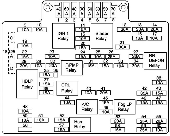
Instrument-panel fuse block. This block is located at the driver’s-side edge of the dashboard, behind a removable access cover. It contains fuses for body electronics, interior lighting, door locks, rear accessories, and other cabin equipment. It is a logical starting point when diagnosing a failed power outlet, interior lamp, or door-lock function.
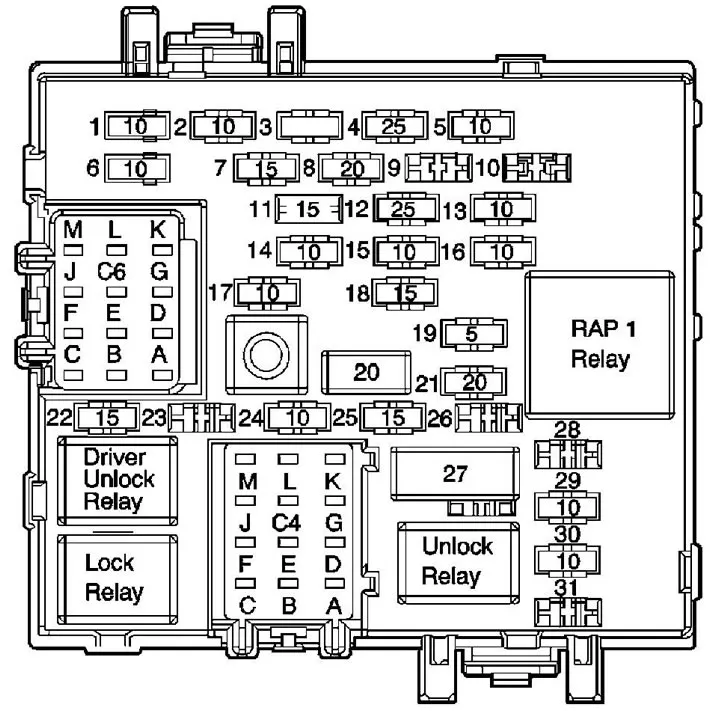
Center instrument-panel electrical block. This unit is positioned underneath the dashboard, to the left of the steering column. Depending on the equipment package, it contains circuit breakers and electrical connections associated with power windows, power seats, and other accessories.
There is one important qualification. Hybrid Tahoes and vehicles with specialized equipment may have additional electrical distribution components. Do not assume that every fuse block shown in a general diagram is installed in every vehicle.
Fuse Ratings and Circuit Assignments
The correct fuse rating is just as important as its location. A fuse with an insufficient rating may open during normal operation, while an oversized fuse can allow wiring to overheat before the circuit is disconnected. Always match the rating specified for the exact vehicle and circuit.
On the instrument-panel fuse block, common protected circuits include the rear seats, rear accessory power outlet, steering-wheel control backlighting, driver door module, interior lighting, turn and stop lamps, door locks, rear climate controls, power mirrors, and selected Body Control Module functions.
Other positions may protect accessory power outlets, interior lamps, rear-seat entertainment equipment, the power liftgate, rear parking assist, the Driver Information Center, the rear wiper, cooled seats, the driver seat module, and remote keyless entry. Availability depends on the model year and installed equipment.
The exact fuse position and amperage must be confirmed using the fuse-block cover, owner’s manual, or factory service information. A circuit’s name alone does not establish its fuse rating. This is especially important in the underhood block, where engine controls, fuel injectors, oxygen sensors, headlamps, and ABS circuits have dedicated protection.
Relay Designations: What the Labels Mean
Relay names are usually more useful than their physical positions when tracing a fault. On the GMT900 Tahoe, underhood labels identify functions such as cooling-fan control, starter operation, fuel-pump operation, headlamps, fog lamps, and the air-conditioning compressor.
Common abbreviations include FAN HI and FAN LO for high- and low-speed cooling-fan circuits, FAN CNTRL for cooling-fan control, STRTR for the starter circuit, and FUEL PUMP for the fuel-pump circuit. HDLP LO or HID refers to the applicable low-beam or HID headlamp circuit, while FOG LAMP identifies the front fog lamps. A/C CMPRSR indicates the air-conditioning compressor circuit.
These labels describe functions, not universal relay socket numbers. A relay’s location, pin configuration, and electrical rating must be confirmed against the correct diagram. Swapping two relays simply because they look alike is not a reliable diagnostic method; their internal wiring and current capacity may differ.
For additional reference material, www.chevyman.ru can help technicians find Chevrolet repair information and wiring diagrams. Cross-check any secondary reference with the factory documentation for the specific vehicle.
How to Diagnose a Failed Fuse or Relay
A systematic approach is usually faster than replacing parts on suspicion. If a Tahoe’s fuel pump, headlights, power outlet, or cooling fan stops working, begin with the affected circuit and its power supply.
First, confirm the symptom. Determine whether the component has failed completely or operates intermittently. Check related functions, warning lights, and diagnostic trouble codes where relevant.
Next, inspect the correct fuse. Switch off the ignition and follow the service procedure before removing it. A visual inspection can reveal a broken element, but a continuity test or suitable electrical measurement provides better confirmation.
Then investigate why the fuse failed. A replacement that blows immediately often indicates a short circuit or excessive current. Inspect the wiring, connectors, and connected component rather than fitting another fuse repeatedly. Repeated fuse failures are symptoms of an unresolved electrical problem, not a reason to install a higher-rated fuse.
When testing a relay, check the supply voltage, control signal, ground, and switched output according to the wiring diagram. A relay click does not prove that its contacts can carry current under load. Corroded terminals, damaged wiring, and poor ground connections can produce symptoms that resemble a failed relay.
Finally, install the specified components, restore all covers, and test the system under the conditions that originally caused the fault. Never replace a fuse with one of a higher amperage, bridge its terminals with wire, or probe airbag and hybrid high-voltage circuits without the appropriate training and equipment.
Final Checks Before Returning the Vehicle
The Chevrolet Tahoe’s fuse and relay system becomes much easier to service once the correct distribution block, circuit label, and wiring diagram are identified. Yet there is no single universal fuse list for every GMT900: model year, optional equipment, engine choice, and hybrid configuration all matter.
For workshop use, record the vehicle identification number, verify the relevant diagram, and confirm the replacement’s amperage and specification before installation. These small checks prevent repeat failures and protect expensive control modules. In electrical diagnosis, the right component is only half the answer; understanding why it failed is what makes the repair last.